Change the View Range to display these elements
Activate T.O. Footing
Hide the column grids
Properties - Underlay: 1st Floor
Extents - View Rang: Edit

Top: Level Above (Basement), Offset: 2300
Cut plane, Offset: 1200
Bottom: Unlimited
View Depth
Level: Unlimited
Architecture tab > Build panel > Wall
Type Selector - Basic Wall: Generic - 225mm Masonry
Properties
Location Line: Core Centerline
Base Constraint: T.O. Footing
Base Offset: 0.0
Top Constraint: Up to Level: 1st Floor
Top Offset: 0.0
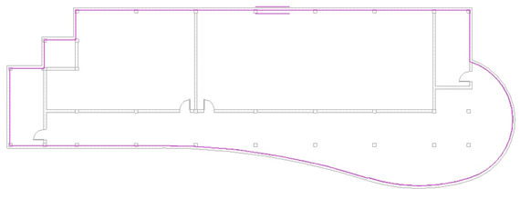
Draw panel > Pick Line
Hover cursor over wall, press [Tab] until the centerline display
Select the exterior walls, stair and elevation walls

Finish the curved wall before pick the straight wall

Drag this wall end to join the bottom wall

Click Modify to end the command
Properties - Underlay: None

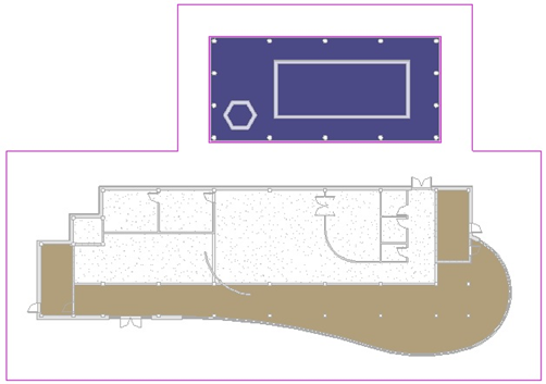
Change to 3D view
Add Footing to the Walls
Activate T.O. Footing plan
Type Selector - Base Wall: Generic - 600mm Concrete
Properties
Location Line: Core Centerline
Base Constraint: T.O. Footing
Base Offset: -450
Top Constraint: Up to Level: T.O. Footing
Top Offset: 0.0
Draw panel > Pick Line

Properties
Location Line: Core Centerline
Base Constraint: T.O. Footing
Base Offset: -450
Top Constraint: Up to Level: T.O. Footing
Top Offset: 0.0
Draw panel > Pick Line

Press [Tab] to pick the centerline of the wall

Change to 3D view