Add Recessed Ceiling and Soffit to the breakfast area
Activate Ceiling Plan - 1st Floor
Select Grid Line, Section and Elevation Mark, then type VH to hide them
Architecture tab > Build panel > Ceiling
The default ceiling grid is 600 x 1200mm
Select one grid in each restroom
Type Selector - Compound Ceiling 600 x 600mm Grid
Properties palettes - Height Offset from Floor: 2750
Add Ceiling Components
Architecture tab > Build panel > Component
Mode panel > Load Family
US Metric folder\ Lighting Fixture\
M_Downlight Recessed Can.rfa
M_Troffer Light-Parabolic Square.rfa
M_Troffer Light_Parabolic Rectangular.rfa
Mechanical Equipment folder\
M_Square Return Register.rfa
M_Square Supply Diffuser.rfa
Use Aligned command align the components with the grid lines
Create Ceiling and Soffits
Architecture tab > Build panel > Ceiling
Ceiling panel > Sketch Ceiling
Draw panel > Line
Draw rectangle in the hallway, click Finish
Type Selector - Compound Ceiling: Plain
Properties palettes - Height Offset from Level: 3050
Activate East-West Section view
Return back to 1st Floor Ceiling plan
Architecture tab > Build panel > Wall
Type Selector - Basic Wall: Soffit 13mm GWB & Metal Stud
Properties palettes
Location Line: Finish Face Interior
Base Offset: 3050
Top Constraint: Up to Level: 2nd Floor
Top Offset: -300
Draw the line across the face of the ceiling
Activate 1st Floor plan
Quick Access Toolbar > Camera
Create a camera view looking at the ceiling
Press Ctrl + Tab return back to Ceiling 1st Floor
Architecture tab > Build panel > Component
Type Selector - M_Down Light- Recessed Can 152mm Incandescent - 120V
Place 3 Recessed Lights on the plain ceiling
Modify panel > Geometry panel > Join Geometry
Select the ceiling, then select the soffit wall
It joins into one
Add a Recessed Ceiling
Activate 1st Floor Ceiling plan
Pan over the breakfast area
Architecture tab > Build panel > Ceiling > Sketch Ceiling
Draw panel > Circle
Type SC then select the curved wall, this will snap to the center of the curved wall
Draw the outline of ceiling, then draw an opening of 2400mm
Click Finish
Type Selector - Compound Ceiling - Plain
Properties palettes - Height Offset from Level: 3050
Select the ceiling, Mode panel > Edit Boundary
Draw lines along walls, then Split Element (Delete Inner Segment)
Architecture tab > Build panel > Wall
Type Selector - Basic Wall: Soffit - 13mm GWB & Metal Stud
Properties palettes -
Location Line: Finish Face Interior
Base Constraint: 1st Floor
Base Offset: 3050
Top Constraint: 1st Floor
Top Offset: 3650
Draw panel > Pick Line
Select the inner circle
A soffit wall height 600 (3650 - 3050) created at the inner circle
Architecture tab > Build panel > Ceiling
Ceiling panel > Sketch Ceiling
Draw panel > Pick Wall
Select the outer edges of soffit wall, click Finish
Type Selector - Compound Ceiling - Plain
Properties palettes - Height Offset from Level: 3650
A ceiling created on the soffit wall
Activate 1st Floor
Create a camera view looking toward the breakfast area
Attach Wall to Ceiling
Activate East-West Section view
Zoom in to the breakfast area, select the arc wall
Modify Wall panel > Attach Top/ Base
Click OK
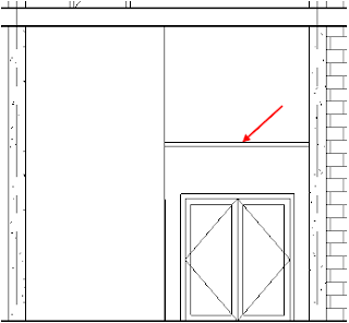
Arc wall extend to the height of the ceiling, but not attach to the ceiling
Height of Wall after Attached
Select arc wall
Properties palettes - Unconnected Height: 2500
The wall height not updated
QAT > Aligned dimension
The actual height after attached is 3050


